
DÒNG LECP6/DÒNG LECA6 - SMC
Mô tả
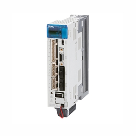
Controller (Step Data Input Type) LECP6 (Step Motor) / LECA6 (Servo Motor) Series Specifications
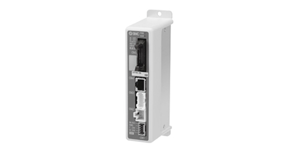
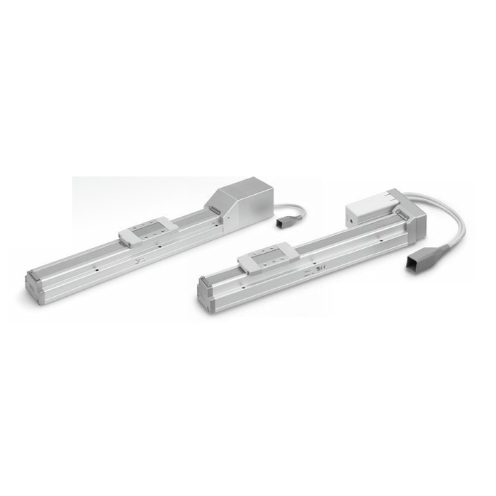
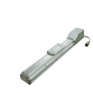
Step motor (24‑V DC servo) LECP6 Series external appearance
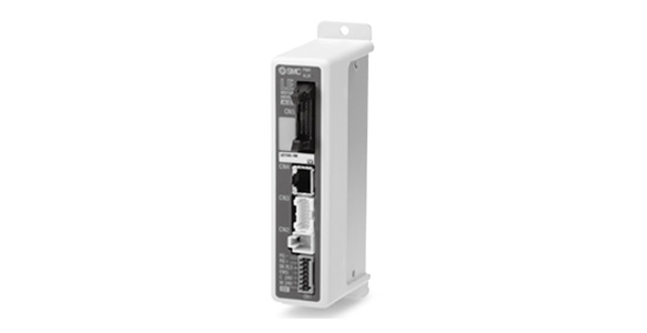
Servo motor (24 V DC) LECA6 Series external appearance
| Item | LECP6 | LECA6 |
|---|---|---|
| Compatible Motor | Step motor (24‑V DC servo) | Servo motor (24 V DC) |
| Power Supply Specifications Note 1: | Power voltage: 24 V DC ±10% Note 2: [Including motor drive power, control power, stop, lock release] |
Power voltage: 24 V DC ±10% Note 2: [Including motor drive power, control power, stop, lock release] |
| Parallel Input | 11 inputs (photo-coupler isolation) | |
| Parallel Output | 13 outputs (photo-coupler isolation) | |
| Compatible Encoder | Incremental A/B phase (800 pulses/rotation) | Incremental A/B (800 pulses/rotation) / Z phase |
| Serial Communication | RS485 (Modbus protocol compliant) | |
| Memory | EEPROM | |
| LED Indicator | LED (green/red), 1 pc. each | |
| Lock Control | With forced-lock release terminal Note 3: | |
| Cable Length [m] | I/O cable: 5 or less, Actuator cable: 20 or less | |
| Cooling System | Natural air cooling | |
| Operating Temperature Range [°C] | 0 to 40 (no freezing) | |
| Operating Humidity Range [%RH] | 90 or less (no condensation) | |
| Storage Temperature Range [°C] | -10 to 60 (no freezing) | |
| Storage Humidity Range [%RH] | 90 or less (no condensation) | |
| Insulation Resistance [MΩ] | Between housing and SG terminal: 50 (500 V DC) | |
| Weight [g] | 150 (screw mounting type), 170 (DIN rail mounting type) | |
Note 1: Use a power supply other than the "inrush current prevention type" for the controller input DC power supply. When conformity to UL is required, use with a UL1310 Class 2 power supply.
Note 2: The power consumption changes depending on the actuator model. Refer to the actuator specifications for more details.
Note 3: Compatible with non-magnetizing lock.
Dimensions
(Units: mm)
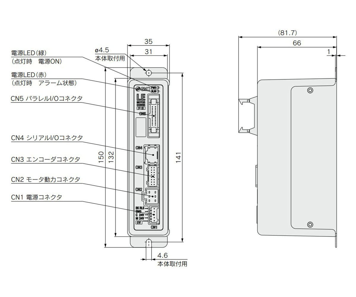
Screw mounting (LEC□6□□-□) dimensional drawing
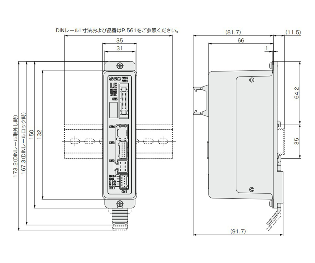
DIN rail mounting (LEC□6□□D-□) dimensional drawing
*Refer to the manufacturer's catalog for DIN rail L dimensions and part numbers.
Mounting Methods
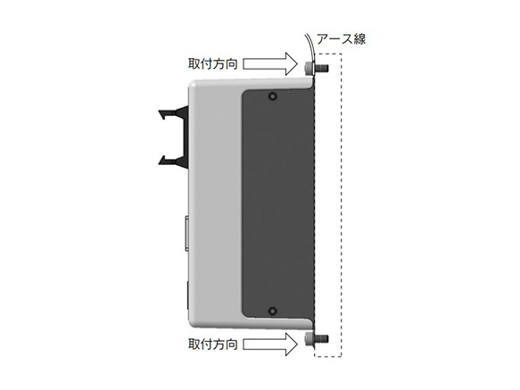
Screw mounting (LEC□6□□-□) (use 2 × M4 screws)
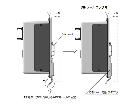
DIN rail mounting (LEC□6□□D-□) (use DIN rail)
Wiring Example 1 (Power Supply Connector: CN1)
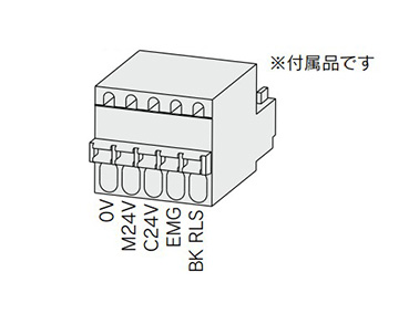
Power supply plug for LECP6 (image of LEC-D-1-1)
CN1 Power Supply Connector Terminals for LECP6
(FK-MC0.5/5-ST-2.5)
| Terminal Name | Function | Function Details |
|---|---|---|
| 0 V | Common supply (-) | M 24‑V terminal / C 24‑V terminal / EMG terminal / BK RLS terminal are common (-). |
| M24V | Motor power supply (+) | Motor power supply (+) side supplies to the controller. |
| C24V | Control power supply (+) | Control power supply (+) side supplies to the controller. |
| EMG | Stop (+) | Input (+) for releasing the stop. |
| BK RLS | Lock release (+) | Input (+) for releasing the lock. |
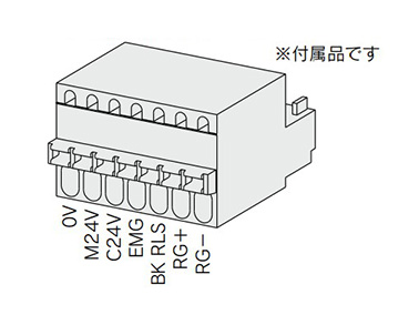
Power supply plug for LECA6 (image of LEC-D-1-2)
CN1 Power Supply Connector Terminals for LECA6
(FK-MC0.5/7-ST-2.5)
| Terminal Name | Function | Function Details |
|---|---|---|
| 0 V | Common supply (-) | M 24‑V terminal / C 24‑V terminal / EMG terminal / BK RLS terminal are common (-). |
| M24V | Motor power supply (+) | Motor power supply (+) side supplies to the controller. |
| C24V | Control power supply (+) | Control power supply (+) side supplies to the controller. |
| EMG | Stop (+) | Input (+) for releasing the stop. |
| BK RLS | Lock release (+) | Input (+) for releasing the lock. |
| RG+ | Regenerative output 1 | Regenerative output terminals for external connection. (Not necessary to connect them in the combination with the LE Series standard specifications.) |
| RG- | Regenerative output 2 |
*Power supply plug is an accessory. AWG20 (0.5 mm2) cover diameter 2.0 mm or less
Wiring Example 2 (Parallel I/O Connector: CN5)
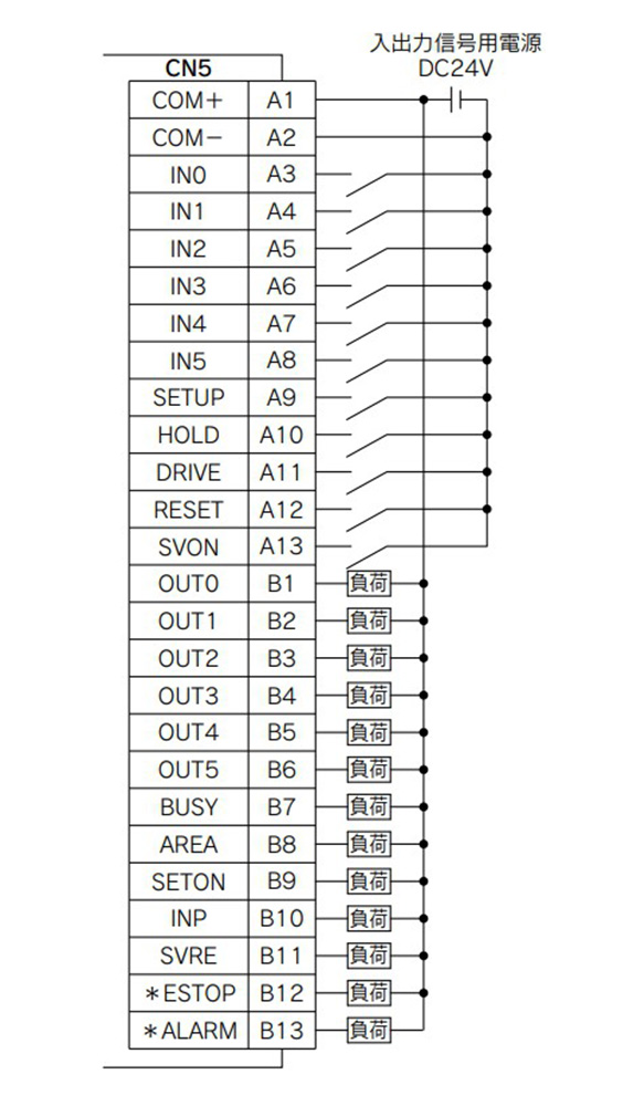
LEC□6N□□-□ (NPN) wiring diagram
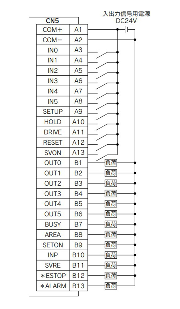
LEC□6P□□-□ (PNP) wiring diagram
Input Signal Details
| Name | Details |
|---|---|
| COM+ | Connects the 24‑V side of the 24‑V DC power supply for the input/output signal |
| COM- | Connects the 0‑V side of the 24‑V DC power supply for the input/output signal |
| IN0 to IN5 | Step data specified Bit No. (Input is instructed for the combinations IN0 to 5) |
| SETUP | Instruction to return to origin |
| HOLD | Operation is temporarily stopped |
| DRIVE | Instruction to drive |
| RESET | Alarm reset and interruption of operation |
| SVON | Servo ON instruction |
Output Signal Details
| Name | Details |
|---|---|
| OUT0 to OUT5 | Outputs the step data no. during operation |
| BUSY | Outputs when the actuator is moving |
| AREA | Outputs within the step data area output setting range |
| SETON | Outputs when returning to origin |
| INP | ON when target position or target force is reached (Turns ON when the positioning or pushing is completed) |
| SVRE | Outputs when servo is ON |
| *ESTOP Note: | No output when EMG stop is instructed |
| *ALARM Note: | No output when alarm is generated |
Note: Signal of negative-logic circuit (N.C.)
- *Use an I/O cable (LEC-CN5-□) when connecting a PLC, etc., to the CN5 parallel I/O connector.
- *The wiring changes depending on the type of controller parallel input/output specification (NPN, PNP specification).